Showing posts with label Layout Construction. Show all posts

Sunday, July 8, 2018

Refining the Track Plan

Last Friday could be considered a fruitless evening because we didn't permanently attach track, however, it would be a preposterous claim in fact.


It was an occasion to set tracks on the benchwork in their planned location and see if things could be improved from a visual perspective but also for operation. Sometimes you move a track half an inch and get a totally different result.


It was also a good occasion to decide where and how the structures would be. The feedmill will be framed on the layout in such a fashion we will be able to include the very photogenic 1950s store brick facade. A few houses will also be scratchbuilt to better grasp the feeling of a small rural town in Southern Quebec.


The next step will be to fix permanently the tracks and tackle the Central Valley double span truss bridge that is quite a challenge in itself. Bridge piers and abutments will probably be 3D printed according to prototype.

Tuesday, July 3, 2018

Ready For Track Laying

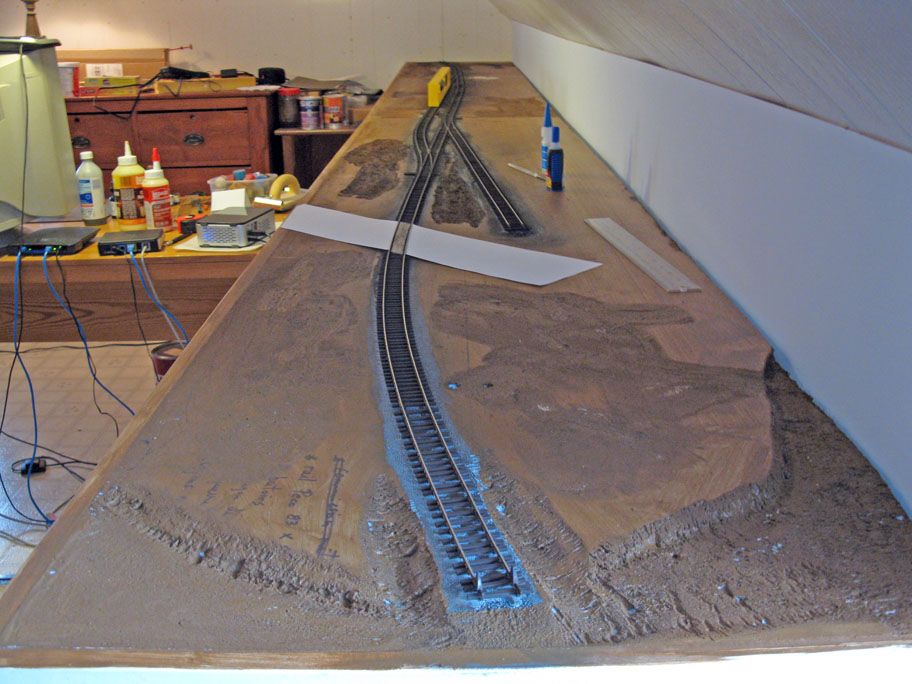
Since the St-Pie layout is a summer building effort, we have to make decent steps forward to ensure the project move along. One such step was gluing down cork sheet on the plywood to create a suitable roadbed for track laying.

In real life, terrain in St-Pie is extremely flat, so we decided to install the cork all over the place. Small variations in topography will be done later by using some putty or universal mud or anything suitable.

Cork and new light fixtures.

This step is also important because from now, Jérôme can work by himself at his own pace. He's our master track layer on the club layout and I certainly expect he will do a good job.

Interestingly enough, Jérôme wants to nail down the track instead of gluing it. He has often advocated for this in the past. Nailing track is no longer considered "professional" nowadays with everybody gluing the track down. While it is debatable, his opinion is you should never permanently glue your tracks before having operated the layout for a while to trouble shoot your work and see if the planned design is really up to the task. It may be a matter of moving a turnout one inch or two to get better results or simply realign a siding a little bit for clearance. Once everything has been worked out, you can glue and ballast the track... or simply keep the nails there if it doesn't bother you that much.


I'm most admit I'm pretty curious to see how operating such a minimalist layout will turn out. We really went on a limb with this one and I hope it can project long lasting interest for an operator.

Saturday, June 23, 2018

Cheap Lighting, Good Results

Over the the years, most have been said about layout lighting. You can waste enormous time reading online articles, printed press and a plethora of comments without ever doing anything close to lighting your layout.

A few years ago, I added lighting in my office room to bring some life to my figure collection displays. Basically, it was a series of small projectors on a track with LED lamps. Nothing fancy, but more than enough for the task and still good looking. I was pleased by the amount of light and ease of pivoting each lamps. As you can guess, from time to time, I did display trains on the shelves and thought to myself it would be a decent way to light a small layout.

Forward a few years to yesterday. To light Jérôme's layout, which is about 13' x 11', we used three of these track lights, one for each module. This time, instead of 3000K LED, we went with daylight 5000K. At first, it looked awkward, but in a matter of a few minutes, we couldn't tell the difference. Better, color rendition on locomotives and cars was up to the task and thus we kept the 5000K lamps.

I won't go in detail, but we found out a 3-projector track light was good enough to light an 8 foot long layout module when installed about 2 feet from the fascia. Depending on module geometry more or less lights can be needed. Another positive thing is you can orient the lamps in such a way to put emphasize on certain part of the layout, which bring some life on what we see.

Another positive aspect of track lights is they don't require complex wiring, use easily available standard components, don't need to build valence and can be located anywhere in a room. That last point is important because lights to close to the fascia cast very unrealistic shadows on model. With track lighting and no valence, you can locate the lights were they are more optimal. They look good and deliver a substantial amount of light economically. We spent about $110 on fixtures and LED bulbs to light about 20 linear feet of layout which is quite decent given the results.

I wouldn't be surprised we will soon update certain parts of Hedley-Junction to take advantage of this new lesson.

Thursday, June 14, 2018

St-Pie Layout Progress Update

Over the last few weeks, I've been working almost "full" time on the grain hopper fleet, altering, renumbering and weathering them to better reflect how they looked circa 2006-2008. I don't expect to finish that as soon as I would like, but I've set myself the goal of weathering all the rib-sided cars first then move on working on something else.

Jérôme and I also worked a tentative set of steps to achieve for the layout. No deadlines are set because his working schedule is highly atypical and we get very little time to work together. Since Jérôme is highly proficient at track laying, wiring and scene detailing and I'm bettter at scenery, rolling stock and structure building, we decided to divide the work between us in such a way we can optimize each steps.


To be honest, under most normal circumstances, this project would fail if expectations, resources and time available aren’t taken in account. This is why we decided to define our goals according to what can actually be done. The first thing that must be taken into account is the fact I won’t have access to the layout itself often. At best, once a month, probably less. It means a lot of stuff only me can do will have to be done on my benchwork then delivered to Jérôme for installation.

In that regard, it means scenery work (ground cover, grass, vegetation, river, etc.) will have to be kept to a minimum so they can be done efficiently in one session. The only way to achieve that is to minimize our expectations. It means we won’t go crazy over hyper-realistic scenery, but we will be careful to do a decent job, focussing on correct colors and textures based on the prototype. Given Jérôme’s focus is operation, this trade off isn’t that bad.

Thus, here’s the goals we set for ourselves:
  • Lay tracks and wire them as soon as possible using readily available components (NCE PowerCab and Peco track);
  • Assemble a realistic fleet of cars (correct prototypes, correct paint scheme, correct amount of weathering for the era);
  • Build required structures as close to prototype as possible. Reuse existing structures when possible, model only what was there;
Once these goals will be achieved, stuff like scenery, details, road vehicles and other secondary items will be added accordingly. 
 
Things we won’t do are backdrops (painted or photo), over the top scenery and tricky structure details. The goal is to get the sense of the place to support realistic operation. These things can be added at a later time but shouldn’t be important at first.

Tuesday, May 29, 2018

St-Pie Layout - Benchwork Completed and Installed

I didn't promise extensive reports about this project, but I'm glad to announce the benchwork is now built and found its way in Jérôme's home.


The benchwork was built in three separate modules in Louis-Marie's workshop that could be easily loaded in Jérôme's car for a 2-mile trip to their final destination. Benchwork is quite lightweight and built with a typical ladder-style 1" x 4" frame. 1/4" lauan plywood was used. I know it's not bullet proof, but I used it with success on my Harlem Station layout and given the abuse this layout has suffered, it behaved extremely well under such circumstances.

Wooden legs were also built with T-nuts and bolts for height ajustment. It came really handy since Jérôme's basement floor is a roller coaster. Legs were painted in black to minimize their visual impact. Meanwhile, we haven't decided yet on the fascia color, but white is starting to be a serious option. We initially thought about painting it black, or tan, or simply Pullman green, but when installing the layout, it became apparent the white primer made the layout disappears. We rarely hear about using this color, but we will give it a shot. It seems promising.


Sorry for the extremely crappy photos. I didn't have my camera and Louis shot a few ones with his phone under very bad lighting conditions.

I'm glad to see the project moving forward. Next step will be to lay the cork roadbed and tracks, then add the bridge deck. Then wiring and operation will start. I also started to weather the grain car fleet, starting with old Blue Box kits to hone my skills before moving on pricier and more detail ones.

Tuesday, March 6, 2018

St-Pie Layout Greenlighted


Some progresses occurred during the last weekend about the St-Pie Layout as we shall call it now. A few prerequisite conditions had to be met before we ever ventured into this project, namely finding suitable motive power. A successful trip to Van Horne Hobby in Laval, QC, last Saturday helped us secure a brand new Atlas B39-8 in LMX scheme equipped with a very old original QSI sound decoder… While the paint scheme will require some touch up to match prototype pictures, this is an excellent start for a project.

Once we got the locomotive, we bought a few grain hoppers to complete the fleet. Before visiting hobby shops all over Montreal area, we made sure to survey every rolling stock that could be seen on MMA St-Guillaume subdivision’s pictures. Grain hoppers are costly and we only wanted to purchase relevant material that characterized the road.

A few other items were also acquired, including a pair of Central Valley 150ft Pratt Truss bridges, a Lonestart grain semi-trailer and rooftop details for the future scratchbuilt grain elevators. In that respect, we now have everything on hands to make this project real.


NEW PARAMETERS

Meanwhile, Jérôme has been fiddling with the track plan a little bit over the last week. I certainly think mocking up the layout on the floor was a great thing. While I’m a big fan of over-designing track plans, I know too well scene composition and operation must be tested in real life before committing to a final plan.

Using Google Earth and a measuring tape, Jérôme found out St-Pie runaround could only handle two grain cars at once. Yes, you read well… two cars in 2010. That may sound ridiculous, but it seems MMA deemed it was enough for their needs which is ideal for a small layout. Peculiar operation patterns are bound to happen. This discovery also has an unexpected impact on scene composition. Initially, we placed the grain elevators too far apart. But now, they are closer on the layout, making for a much interesting scene framed by two tall structures. It also means the lead track on the left side is now much longer, which is indeed a positive development.

Finally, another parameter surfaced: the layout must be fully independent from the walls (supported only by legs) and modular for ease of transportation is a move is required. I don’t see it as a constraint since it will be easier to build each module in the workshop and do the messy work there.

So now it’s time to rip some wood and assemble the benchwork… Meanwhile, back to Hedley Junction where I still have a lot to do!

Friday, June 30, 2017

Light & Structure


Yesterday, after few experimentation, I built the lighting rig for the layout. I came to the conclusion I needed two LED strips to get a decent amount of lighting and to avoid unwanted shadows on cars displayed on the main line.


The rig is made of a piece of wood with a beveled side. Another small slightly angled piece is added for the second LED strips. To help dissipate heat and often a better surface for gluing the strips, I applied an aluminium duct tape on both piece after gluing them. I don't have confidence on the strip adhesive thus I added CA glue to make sure the bond was good.


In case of failure, I made sure the lighting is only screwed on the fascia and can be removed easily for maintenance of replacement. So far, I only one strip is alimented but I already have a nice level of light. I'm also quite happy the warm white LEDs really provide an excellent color render.


I also started to build the feed mill cardboard core. As I previously said, the LEGO bricks building help to determine a few things and now I can proceed with the real structure. But I must admit my fear became reality: the feed mill is quite high and when I take picture, I easily see where the sky ends. I suspect I'll have to make the backdrop at least 4 inches higher to make things looks good. It means the shadow box will have to be expanded accordingly. I'm not sure how I will do it, but I suspect I'll regret not making the backdrop higher. On the other hand, I'm quite happy with the proscenium opening, thus it's really the back drop height that is the problem. I've also thought about adding a blue sky ceiling as another less intrusive option but I'm not sure it will be visually very interesting.


Friday, June 23, 2017

Progress and LEGO Mockup

I'm glad to announce the module and it's fascia are completed. Everything was sanded down, primed and sanded again to get a nice smooth finish that will look good in my office room. I wasn't sure about the color to use, but finally settled down to the tried and true black as so often used by British modellers. Honestly, I'm quite happy with the result and can't wait to add the last coat this evening.


I also decided to make a scale mockup of Moulée St-Pie feed mill. Honestly, the structure probably date back to the 1950s and is far larger than our usual grain elevators. The main building is a tower with a 50ft x 50ft footprint flanked with two other 50ft x 50ft warehouses.


I wasn't eager to waste material making a mock up so I decided to use LEGO bricks and make one as close as possible to the prototype. Honestly, it turned out far better than I thought. I was also able to use a LEGO rolling door as can be seen on the real building. It would make a very interesting feature on the layout and I'm actually thinking about including LEGO parts inside the final structure. I suppose it could be activated with a fairly simple hand-activated mechanism.


However, all things being good, I must admit the structure looks quite tall and I'll need to adjust the dimensions a little bit to better fit the space available and make sure it looks good.


As a side note, I consider one could use LEGO bricks to make sturdy structure cores. Aftermarket parts can be bought at good prices online and would ensure building wouldn't warp. Being plastic, you can glue styrene and other materials to it just like we do with styrene cores. I don't know if it would be economically viable with Moulée St-Pie, but it wouldn't hurt to try something out.

Thursday, June 22, 2017

A Module

The baseboard and fascia are now progressing at a decent pace which means going small is also a way to ensure progress is steady and rewarding. That may sound cheesy, but it's an important motivational factor. That should never be underestimated.


I'm also starting the assembly of a Sunset Valley garden train switch stand to operate the Peco turnout. The idea is not new and was pioneered a few years ago by Trevor Marshall on his excellent S scale Port Rowan layout. This is probably the most prototypical way to operate a turnout and I'm certainly eager to try it out. It makes sense on a small switching layout where every prototypical moves are reproduced to bring life to the models.


Sunday, June 18, 2017

QSSR Mark III

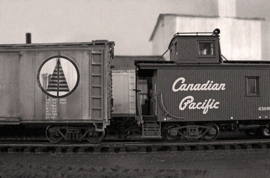
Good news my friend, as promised, the QSSR is back on track, this time as a 48" x 18" portable layout. As always, it is set in Quebec's Eastern Township, will deal with a local feedmill on a derelict branchline remnant and is served by our good old Canadian Pacific Railway. If you want to route if a little bit more into reality, it is yet again based on ex-Maine Central's Hereford Railway branch. Until the mid-1980s, a chunk of the former line was still used to reach a few customers in Sawyerville, a few miles south of Cookshire. As you can guess, this is really just an excuse for inspiration since I'm not fond of fantasy layouts.

However, the approach will be different as described in this post I made on Hedley-Junction. QSSR is perfect to try this approach and go fully artistic with the project. While I gave a lot of thoughts about the operation aspect of the layout, I'm approach it as a canvas.  Rails and trains will be a part of the picture, but not the main focus. Will it pay off? Maybe, maybe not. But at least, I need to try it out once to see if my ideas are sound and worth implementing on my other projects (Hedley-Junction and Connors). It is also a good occasion to operate a little bit at home as I once did with the original QSSR. I miss that time!

As we speak, the baseboard is completed and I'm soon make the proscenium as often seen on British exhibit layouts.

Oh, and you probably want a track plan? No need for one... A mainline, a turnout and a  siding: yes, the proverbial one turnout layout as originally envisioned.

Saturday, May 9, 2015

A Reboot?

It's been a year since this project have been put aside. It was the time to restore my office room to its former late 19th century splendor.

I now have the time and place to reboot this project again. This time, I'll make it simpler. When I stored the layout, I ripped the turnout because I needed them for the club layout. Thus, I have to rebuild the track again. However, I'm planning to build a one-turnout layout since operation in St. Pamphile is going to be spartan. I remember Lance Mindheim's article about that in MRH last year. I really think, for a small home layout, it is the way to go.

My idea is that I don't need that much a runaround. Also, I'd like the idea the railway company came and ripped off the unused turnouts to rebuild where they were needed, just like the real prototypes do.
On another hand, I have 4 Walthers grain silo doing nothing except gathering dust. I willing to use them to modernized and enlarge my feedmill so it looks like an industry big enough to sustain minimal freight traffic.

Now, at this point, I'm thinking about what I'll do with the benchwork. I'd like it to be less bulky, but maybe I'll keep it as is.

Also, the layout will be much shorter. It used to be 13 feet long. Not it will be 9 feet long with a removable 3 feet cassettes. It will make operation a little bit more tricky, but that's fine with me. In fact, today I was talking with Stéphan Vachon from Sartigan Railway and he was retelling stories of switching puzzles he had to solve when he had to handle more cars than his sidings could handle.

Stay tune. By the way, remember this project is mainly done to learn and try new technics.

Wednesday, April 30, 2014

An Overpass

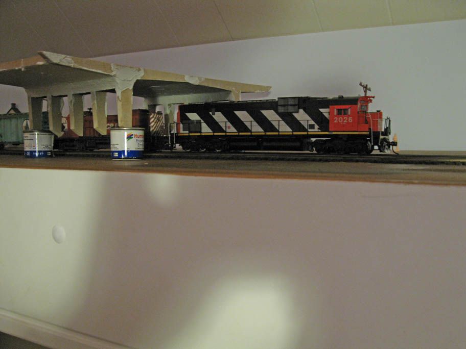
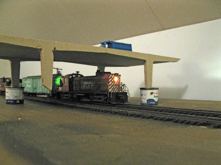
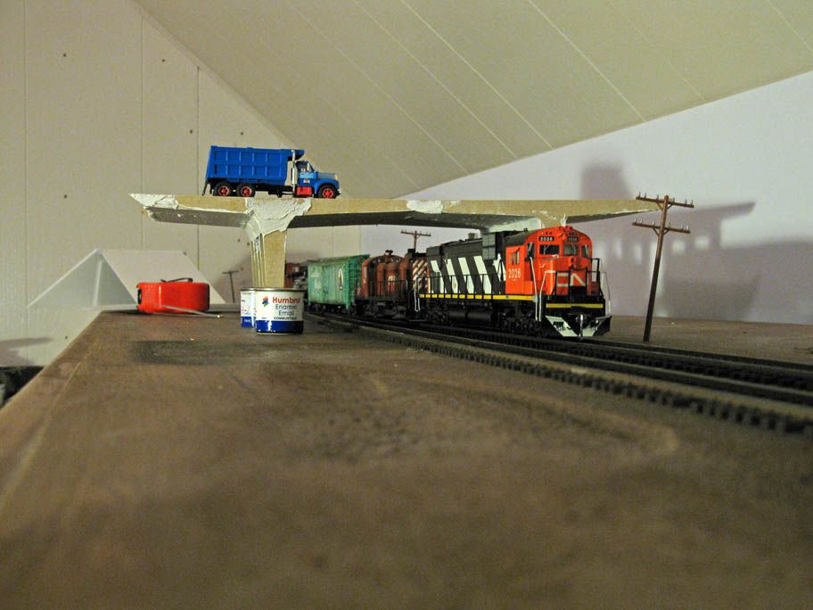
CN 2026 is passing under the new concrete overpass.


My layout is heavily inspired by the old grain elevator near Route Lagueux in St-Nicolas (east to Charny) on CN mainline on Quebec South Shore. At this very place is a typical exemple of a highway access road concrete overpass built in the early 60s when Quebec was developing its highway network.

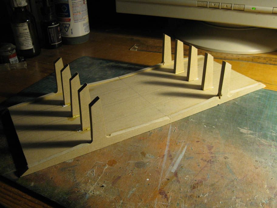
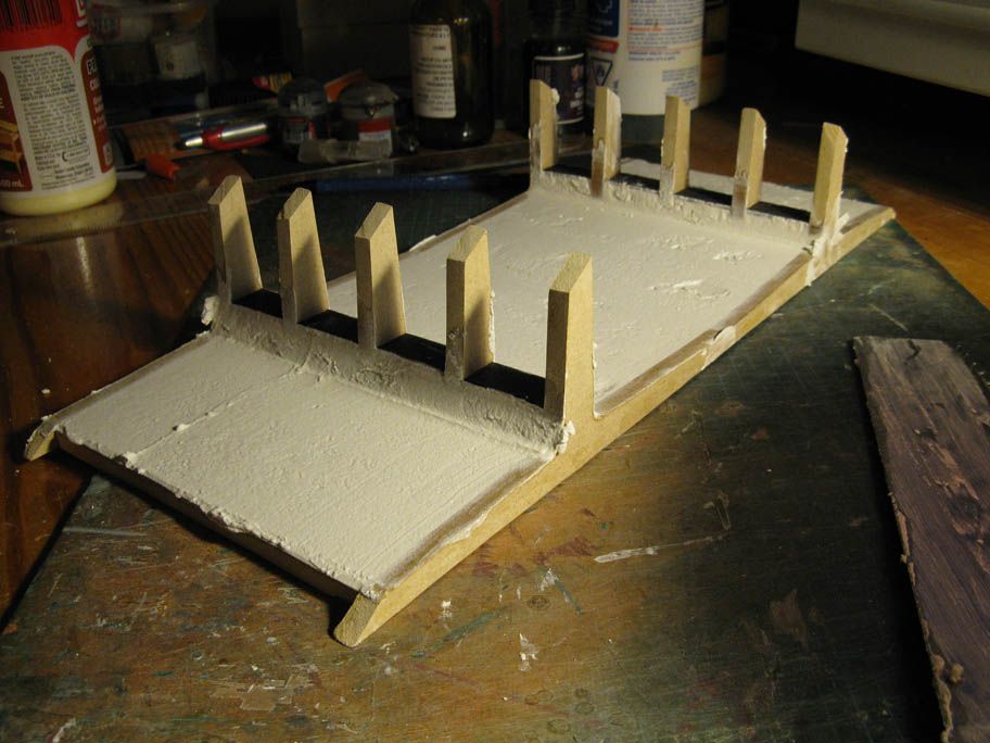
Basic shapes glued together and test fitted.


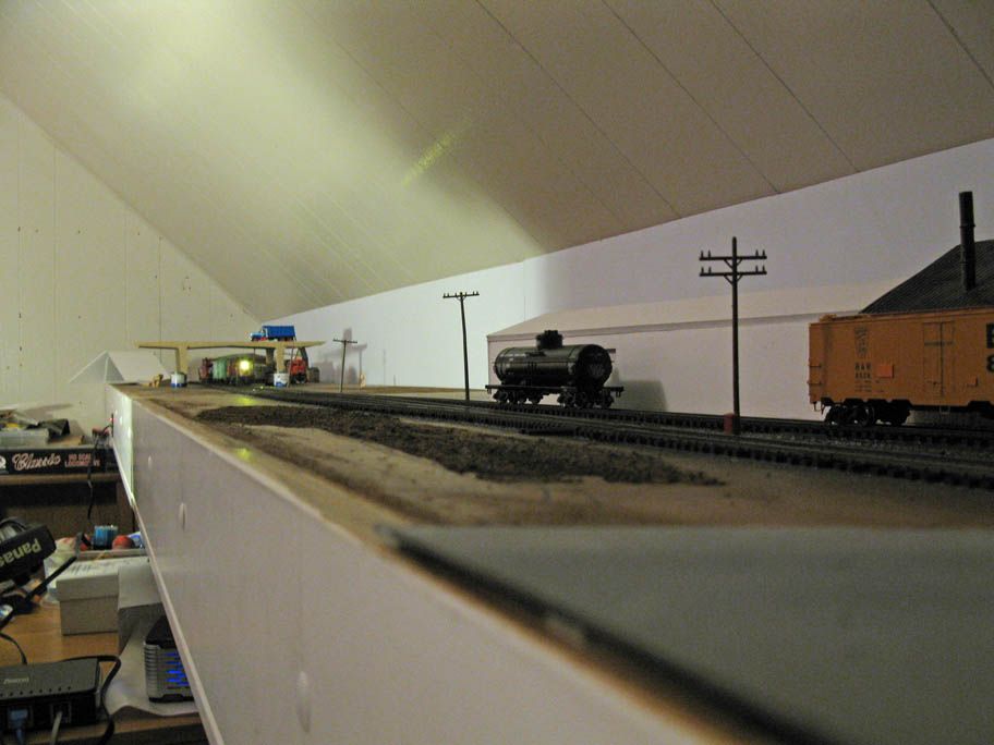
I've always found it a nice locale when I was a kid and my father would drive us to a aunt living in the area. So I decided to make a replica of it to hide the staging area.


The prototype was measured with Google Earth help. Deck and piles are made out of 1/4" MDF. Lots of fun on the table saw! Well, in fact, it was more straight forward than I anticipated.


MDF parts were glued together with carpenter glue and illustration board was used to define the underside of transversal girders. They would be used as lost form when pouring plaster.

Plaster set in place to fill the gaps.

I finally used plaster of Paris to fill the gaps and get an even surface. The back of a saw was used to shape correctly the plaster. Some rough spots are there, but I'll keep them to represent crumbling concrete (eh! Quebec is famous for it's sh*tty concrete infrastructures and poorly built roads... looks like 400 years isn't enough to learn the lesson up there!!!). Joke aside, it will help to get a more realistic look. I often feel plastic kits and styrene lacks the texture to make believeable massive concrete structures.


Monday, April 28, 2014

On The Road Again

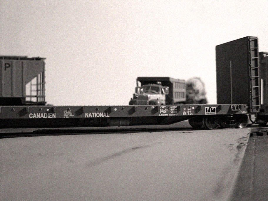
A CN bulkhead flatcar blocks the main road while trucks are patiently waiting.

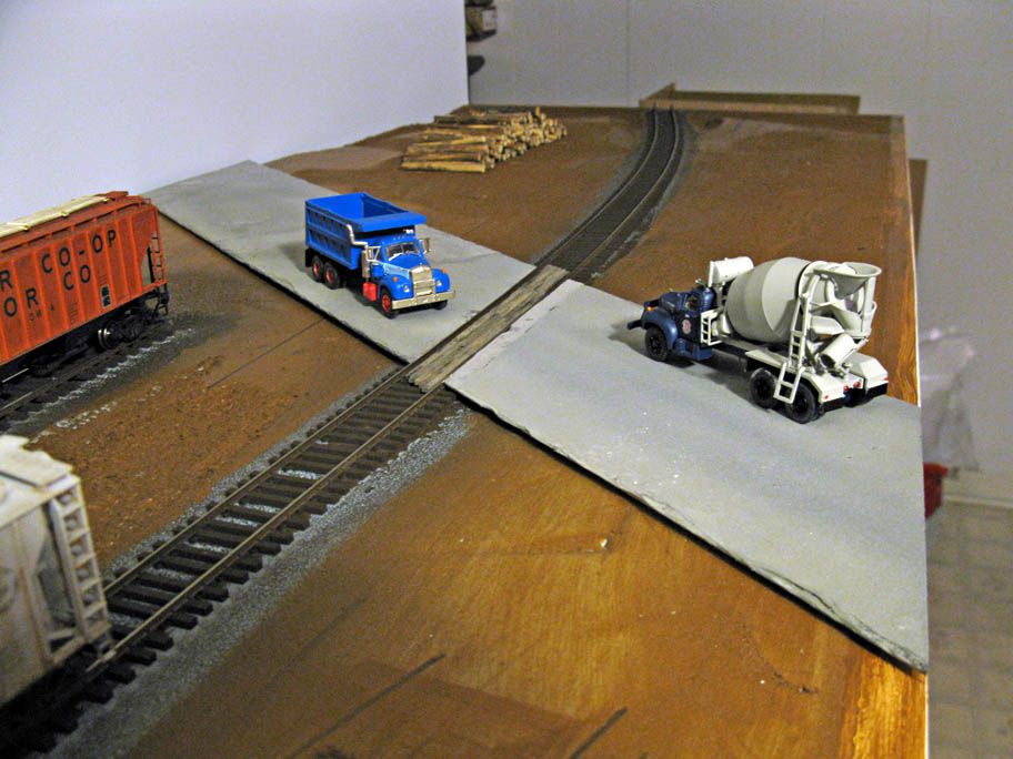
I worked on the road tonight, using a mix of Mindheim and Gravett's technic to make the road. So far, results outdid my expectations. Still lot of weathering to do and also to glue in place the road.


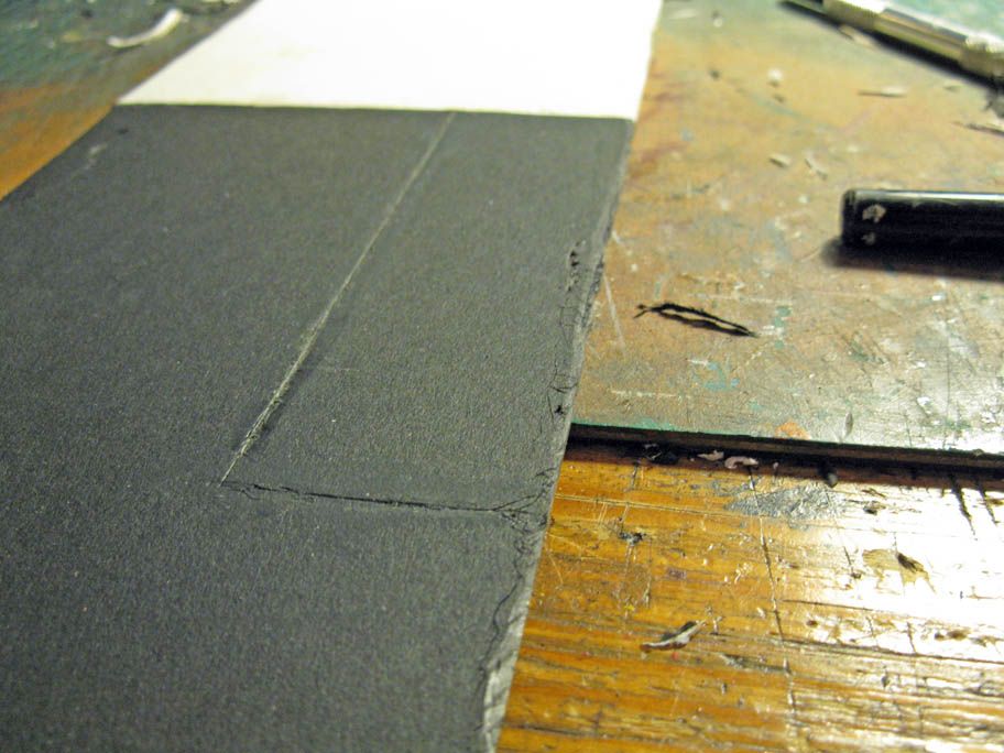
The road itself is made with illustration board and painted with Krylon Camouflage beige and Krylon gray primer. Using an X-Acto blade, I scribbed cracks and also removed layers of cardboard to represent peeling asphalt and potholes.

Distressed the side of the road is a good way to enhance realism.

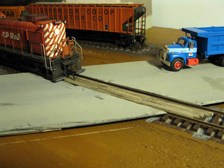
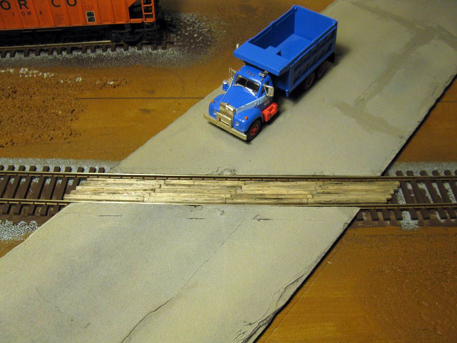
I distressed the road mainly where trucks will quit the main street to go to the feedmill or team track. I used real life pictures of grade crossing to figure out the typical  wear between a road and rails.

The road was particularly distressed were vehicles wheels hit the track.

I only had bits of cardboard, none big enough to cover the entire space in one piece. I didn't care and glued many pieces together with carpenter glue. When dry, I scribbed the joint to make it looks as if each piece was an asphalt patch.


After taking the pictures, I used gloss enamel topped with talc powder to better represent recent asphalt patch on the street. I think Gordon Gravett's technic is fine for some type of road, especially dirty one. But I understand why he said it was often better to only paint tarmac with flat paint. Next step is to paint road lines with my dreaded airbrush.

Sunday, April 27, 2014

Track work completed!


 Yesterday was a productive day. I installed and painted the backdrop and managed to paint the tracks and reassemble the module. So far, so good.


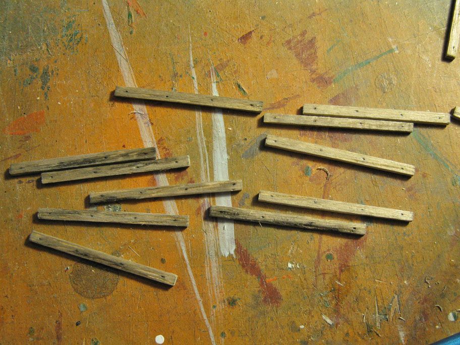
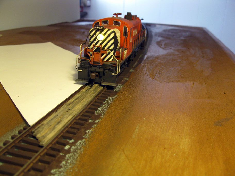
I also installed a wood crossing made of balsa. I distressed the wood to get a more realistic worn out look. India ink washes were used to stain the wood. I'll probably try to get an even more distressed look.


I also did a few operating session this afternoon. It takes about 30-45 minutes to switch the layout with an inbound train of 3 freight cars. These sessions helped me to find out what is good and was is wrong.

On the good side, the feedmill scene work just fine. It's fun to switch and looks pretty good.

However, I'm not that crazy about the runaround. Why? My office room isn't the best out there. It means my desk separate the two module. I have to go around the desk just to move one turnout, which can be frustrating as I have a wired NCE Powercab and the chord just get stuck over my desk. Also, the layout height is 39", which means I'm operating sitting on my chair. Nice to have a realistic view, but really bothersome when wanting to throw that far away switch.

Also, I only have about 24" long beyond the runaround, which makes sorting cars quite difficult when I have more than 3 cars to pull... A real bother...

Another issue is mainly visual. There's little space between the end of the runaround and the wall. It means a train leaving the layout after a session doesn't give the true feeling of definitily going somewhere beyond the layout.

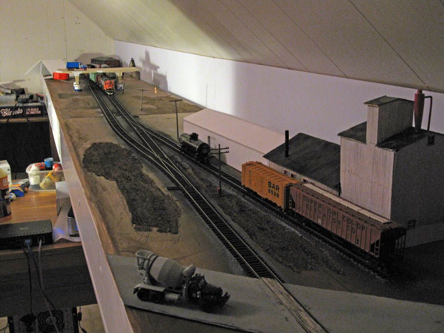
I really want to adress these issues before moving on scenery. First of all, adding an overpass somewhere on the second module would be a good occassion to frame the scene and make the train disappear to some non-descript but scenicked staging area. The overpass would be located somewhere between the runaround turnout and the feedmill (the turnout would be on the staging area).

This solution isn't completely satisfying because the turnout is still far away. I could install a turnout control, but still, means I would have to walk around the desk to uncouple cars, which isn't the best option.

Another option is to remove the runaround an replace is by a stub siding running parallel to the mainline until it reach the right end of the layout. It would means I could not reverse trains anymore on the layout. Is it bad? Not that much. It could means the runaround does exist but somewhere beyond the staging area. I only hate the fact it would means more track density in front of the feedmill. I find this scene to be already crowded enough. Also, that would means track to relay and some rewiring... Well.

I could also see the layout as a throught mainline which is only switched by trains running right-to-left. That could be a very intesresting feature. If doing so, I would had a cassette on the right side, thought it could be quickly a gimmick.

So no, there's no easy way out. I think having a runaround is a double edge sword on a small switching layout. You really need enough place on one end to sort cars. I failed to see that. In fact, I had previously planned another shelf on the left side to have trains disappear to somewhere and have a switching lead. I scrapped the idea, but didn't think it would have an impact on operating pattern.

Anyway, before tearing down what I did, I will just continue to operate a little bit more to find more efficient patterns, just like a real railway would do.